
Projection One is an interactive art installation that was recently unveiled at Harvard's Graduate School of Design. Conceived and built by Andrew Payne and fellow GSD student, Eddy Man Kim, Projection One strives to challenge the way in which users perceive projection art. We started by changing the projection surface. Our idea was simple - take the traditional screen and cut it up into strips of variable widths. Then rotate those strips to create a three dimensional surface; adding depth to create a more volumetric or spatial experience out of the projection schemes. The overall surface measured approximately 13'(length) x 9'(height) x 3'(depth).
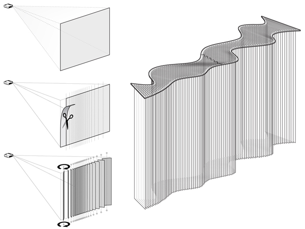
Adding depth to a projection surface only works if the material characteristics of the screen is transparent enough to allow for the light from the projector to pass through. We spent a good deal of time investigating various types of fabrics, and even string; but ultimately found that Tulle provided just the right amount of transparency and material density. Tulle is lightweight net-like fabric traditionally used in wedding veils and other ornamental garments.


Acknowledgements
First, we would like to thank Professor Panagiotis Michalatos. It is without a doubt that this project would not have been realized without his tremendous help and support. All of the visualizations were developed as scripts written in C# and used several of the sawapan motion and audio libraries.
Contact Us
Like what you see or want to know more about how to bring this installation to a city near you? Contact us.


